This guide explains how to efficiently build, edit, and analyze models in ReliaSim using the graphical interface. It is intended for analysts, engineers, and operations teams who want to move quickly—from model creation to insight—using keyboard shortcuts, mouse gestures, and built-in visualization tools. By the end of this guide, you should be able to create a basic flow model, configure key parameters, and interpret core results such as throughput and efficiency.
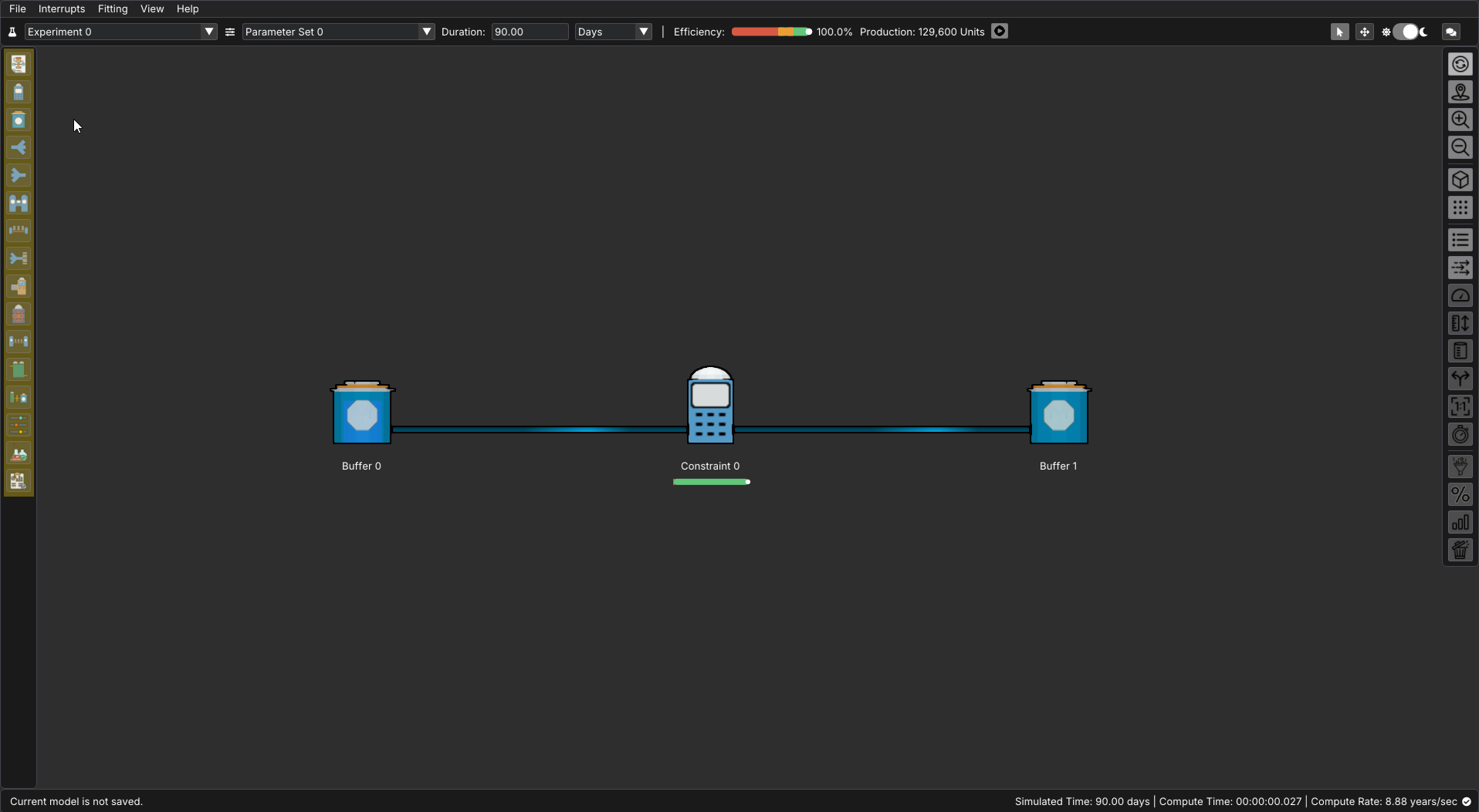
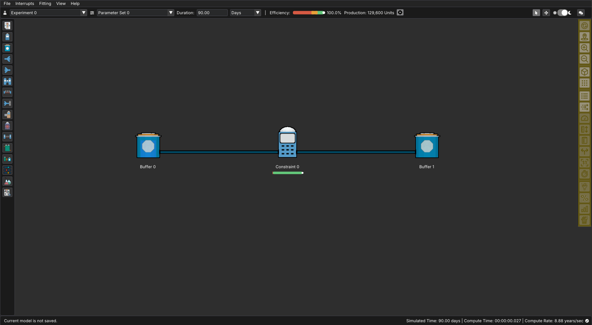
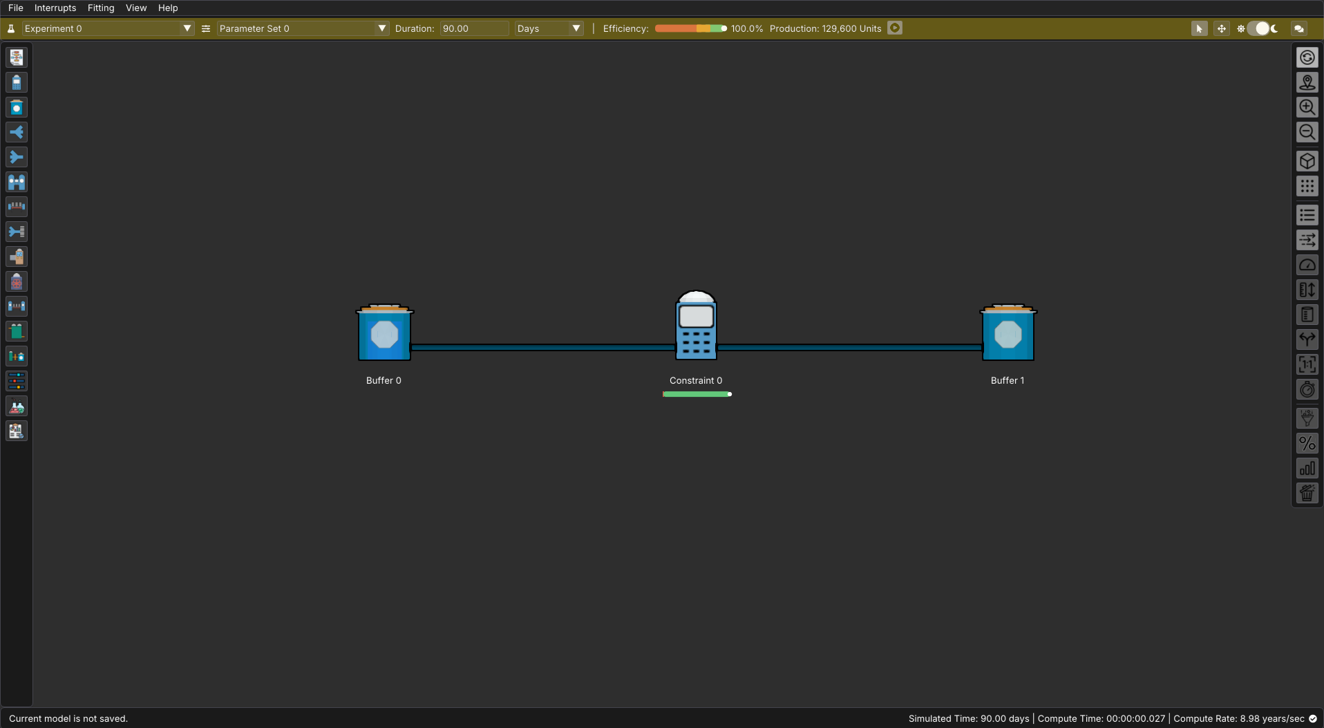
When ReliaSim opens a new file, it starts you with a simple, valid flow: Buffer → Constraint → Buffer. Think of this as a clean baseline rather than a finished model. The first buffer represents an unlimited source of material entering your system, while the final buffer represents everything that leaves the process. Keeping these two buffers intact gives your model a clear beginning and end, which makes results like throughput, efficiency, and flow behavior easier to interpret as your model grows.
From here, begin shaping the middle of the flow to reflect how your process actually works. Replace the default constraint with the steps, equipment, or decisions that matter in your operation—whether that means adding additional constraints, buffers, splits, merges, or batch processes. As you build, focus on the logic of how material moves rather than exact numbers at first. Ask yourself where flow is limited, where material waits, and where it changes form. ReliaSim is most powerful when each node represents a meaningful part of the real system, not just a diagram element.
As you expand the model, continue to treat the first and last buffers as the bookends of the system. The first buffer should always represent everything that could possibly enter the process, and the final buffer should represent everything that successfully exits it. This structure allows ReliaSim to clearly measure what gets through the system and what holds it back. Once the structure feels right, you can begin refining rates, capacities, and interruptions—knowing that the overall flow from start to finish remains well-defined and ready for analysis.
Following this sections are a collection of tools and tables to help you reference and utilize all the options ReliaSim has to offer. Early models don’t need perfect data to be useful. ReliaSim is designed to help you understand flow behavior first—where material queues, where it’s constrained, and how changes ripple through the system. You can always refine rates, capacities, and interruptions later. Your own process data will validate when your model closely matches your process. Most models evolve through iteration. It’s common to adjust structure, swap node types, and refine assumptions as insights emerge. ReliaSim is built to support this kind of exploration.
Keyboard Shortcuts
ReliaSim supports extensive keyboard shortcuts to accelerate model creation and navigation. While all actions are available via the UI, mastering these shortcuts can significantly reduce modelling time.
View Controls
| Shortcut | Action |
|---|---|
| F11 | Toggle fullscreen |
| 2 | Front facing 2D view |
| 3 | Orthographic 3D view |
| + / - | Zoom in / out |
| Mouse Scroll Wheel | Zoom |
| Middle Mouse | Pan |
| Left Click and Drag | Pan (no node selected) |
Node Operations
| Shortcut | Action |
|---|---|
| Ctrl + D | Duplicate node(s) |
| Delete | Delete hovered/selected node |
| Shift + Click | Add or remove node from selection |
| Hold M | Move currently selected node(s) |
| B | Paint mode (quickly place nodes with context menu) |
| Esc | Cancel action / deselect nodes / close open menus / exit paint mode |
| Ctrl + P | Screenshot (Windows only) |
Node Type Quick Keys
When in continuous add mode (after Shift+Clicking from a source node) or after activating Paint Mode (B), press these keys to quickly place nodes. Node hotkeys are the fastest way to build out a flow once you understand your process structure. If you're unsure as to what node to use, add a placeholder buffer or constraint. You can always refine your model after.
| Key | Node Type |
|---|---|
| Q | Buffer |
| W | Constraint |
| E | Split |
| R | Merge |
| T | Conversion |
| Y | Conveyor |
| U | Assembly |
| A | Converter |
| S | Accumulating Conveyor |
| D | Batch Filler |
| F | Batch Processor |
| G | Material Resupply |
Mouse Interactions
Selection & Navigation
| Action | Result |
|---|---|
| Left Click (node) | Select node |
| Left Click (empty space) | Deselect current selection of nodes |
| Right Click (empty space) | Open "Add Node" popup at cursor position |
| Shift + Left Click (node) | Add to or remove from selection |
Node Creation & Linking
| Action | Result |
|---|---|
| Left Click + Drag (from node to node) | Create connection between nodes |
| Left Click + Drag (from node to space) | Create continued node from source |
| Click (in paint mode) | Place node of selected type at cursor |
| Shift + Left Click (drag from node) | Begins continuous add chain. (Release left click to add a node linked to the previous node, select the node type with keybinds or by clicking the context menu, then left click to add the next node in the chain. Click outside the popup to exit continuous add mode). Continuous add mode allows you to extend a flow without reselecting the source node. Click outside the popup or press Esc to exit. |
File Formats
Supported File Types
Model Files:
.aidos- Primary model file format.dys- Legacy model file format (maintained for backward compatibility)*.*- All files (for opening)
Data Export/Import:
.csv- Comma-separated values for data export.json- JSON format for interrupt data
File Operations
| Operation | Shortcut/Access |
|---|---|
| New Model | File → New |
| Open Model | File → Open (shows file dialog) |
| Save Model | File → Save |
| Save As | File → Save As (shows save dialog with default filename) |
| Auto-save | Automatically saves every 2 seconds when enabled under File → Settings, reducing the risk of lost work. |
UI Elements
ReliaSim’s interface is organized into three primary navigation areas—the left, right, and top navigation bars—each designed to support a specific part of the modeling workflow. The left navigation bar is where you configure and edit the structure of your model: defining node behavior, adjusting parameters, setting up experiments, and reviewing results. The right navigation bar controls how your model is displayed, allowing you to toggle visual aids, metrics, and flow indicators directly on the diagram to better understand system behavior. The top navigation bar provides high-level controls and feedback, including experiment selection, key performance indicators, replay tools, and global view options. Together, these navigation bars allow you to move seamlessly from building a model, to visualizing its behavior, to analyzing its performance. The tables below describe each navigation area in detail and explain the purpose of every icon you’ll encounter.
Left Navigation Bar
The left navigation bar includes the editing panes for each type of node, as well as the parameter and experiments settings. It includes the following options
| Icon | Name | Description |
|---|---|---|
| Flowchart Editor | Shows a text breakdown of the nodes and connections in the current model | |
| Constraint Editor | Inspect and modify constraint nodes in the current model. A constraint limits the flow rate of material and can experience interrupts. | |
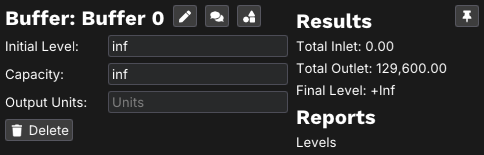
| Buffer Editor | Inspect and modify buffer nodes in the current model. A Buffer is a storage node with capacity and volume tracking. | |
| Split Editor | Inspect and modify split nodes in the current model. A split takes one input and divides it across multiple outputs. | |
| Merge Editor | Inspect and modify merge nodes in the current model. A merge takes multiple inputs and causes them to flow into one output | |
| Conversion Editor | Inspect and modify conversion nodes in the current model. A conversion node handles a change in material from one form to another. | |
| Conveyor Editor | Inspect and modify conveyor nodes in the current model. A conveyor node facilitates transit with volume tracking. The volume held on the conveyor is cannot accumulate. | |
| Assembly Editor | Inspect and modify assembly nodes in the current model. An assembly combines multiple components into one new form. | |
| Converter Editor | Inspect and modify converter nodes in the current model. A converter is a single node representing the same as a conversion and constraint node together. | |
| Material Resupply Editor | Inspect and modify material resupply nodes in the current model. A material resupply node is effectively a material supply buffer and a constraint as one node. | |
| Accumulating Conveyor Editor | Inspect and modify accumulating conveyor nodes in the current model. An accumulating conveyor node facilitates transit with volume tracking. The volume held on the conveyor can accumulate to "fill" gaps in capacity. | |
| Batch Filler Editor | Inspect and modify batch filler nodes in the current model. A batch filler is a buffer that undergoes a filling and emptying cycle. | |
| Batch Processor Editor | Inspect and modify batch processor nodes in the current model. A batch processor is a constraint fed by a filling and emptying cycle. | |
| Parameter Set Editor | Shows information and editing options for parameter sets for the current model | |
| Experiment Editor | Shows information and editing options for experiments for the current model | |
| Analysis | Shows compiled results from the current experiment and parameter set |
Within most of the editors shown above, the following menu icons will be available.
| Icon | Name | Description |
|---|---|---|
| Table Editor | Displays a table of all nodes of the selected type within the current model | |
| Form Editor | Displays a list of all nodes of the selected type within the model. Clicking on a node brings up more of the properties for that specific node | |
| Export Settings | Exports the current settings for the selected node type as a .csv file | |
| Import Settings | Imports the current settings for the selected node type as a .csv file | |
| Info | Displays information about the selected node type and it's applications. This is an excellent starting point to asses if a node is a good fit to represent a situation. This option will be available even when there are 0 nodes of the selected type in the current model. This is an excellent starting point when deciding whether a node type fits your real-world process. |
Right Navigation Bar
The right navigation bar controls how your model is displayed and what performance information is visible directly on the flowchart.
The Right Side Navigation Bar primarily deals with how the model is displayed and what information is displayed on the nodes of the model. The icons and their functions are as follows:
| Icon | Name | Description |
|---|---|---|
| Auto Refresh | Toggles whether values displayed under nodes will be automatically updated | |
| Center Focus | Adjusts the screen to center on the original starting point of the model | |
| Zoom In / Zoom Out | Increases or Decreases the magnification of the model. | |
| 3D View / 2D View | Switches between a 3D orthographic view and a 2D side view | |
| Show Grid / Hide Grid | Toggles the display of a grid of dots for the purpose of easy spacing and alignment | |
| Node Names | Toggles the display of the names of nodes underneath them | |
| Connection Direction Animation | Toggles flowing highlights that indicate the direction of material flow | |
| Limits | Toggles the display of the limits under nodes when applicable | |
| Capacities | Toggles the display of the capacity under nodes when applicable | |
| Initial Volumes | Toggles the display of the initial volume under nodes when applicable | |
| Split / Merge Types | Toggles the display of split/merge information under nodes when applicable | |
| Conversion Ratios | Toggles the display of the conversion ratios under nodes when applicable | |
| Interrupt Count | Toggles the display of the interrupt count under nodes when applicable | |
| Throughput | Toggles the display of the throughput under nodes when applicable | |
| Availability / Efficiency | Toggles the display of the availability or efficiency under nodes when applicable | |
| Final Volumes | Toggles the display of the final volume under nodes when applicable | |
| Scrap | Toggles the display of scrap information under nodes when applicable |
Top Navigation Bar
The top navigation bar includes drop downs for selecting experiment and parameter sets, was well as adjusting experiment duration. The rest of the features in this bar are as follows:
| Feature | Name | Description |
|---|---|---|
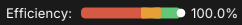 |
Efficiency Gauge | Represents the overall efficiency of the model with the current settings |
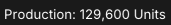 |
Production Throughput | Represents the total quantity produced at the current settings |
| Replay Button | Allows you to replay the simulation on a timeline and see the status of each node at any point along the simulated window. Replay allows you to diagnose bottlenecks, starvation, and blocking by stepping through the simulation timeline. | |
| Cursor | The default navigation mode for adding and editing nodes | |
| Move | Use this option to switch to moving nodes with left-click | |
| Light/Dark Mode | Toggles between the light and dark mode of ReliaSim's UI | |
| Model Comments | Opens a text window where notes or comments can be kept and saved alongside the model. |
The replay feature is one of the most powerful tools in ReliaSim for understanding why your model behaves the way it does. Rather than only viewing final results, Replay allows you to step through the simulation over time and observe how material moves, where it accumulates, and when nodes become blocked, starved, or underutilized. This makes it easier to connect summary metrics—such as throughput and efficiency—to the actual flow behavior that produced them. Replay is best used as a diagnostic aid: when results are unexpected, stepping through the model often reveals the underlying cause within just a few moments.
Node Context Menu
Left-clicking on any node while in cursor mode will open up a context menu. Here you can change and update attributes specific to that node. There are three icons beside the name of the node that offer the following options:
| Icon | Name | Description |
|---|---|---|
| Description | Edits the Description, or specific name, of the selected node. | |
| Comments | Opens a comment window for that specific node. These notes will be saved along with the model and attached to that node. Notes saved here only serve as documentation, and do not impact the function of the model. | |
| Switch Node Type | This feature is presently only available for certain kinds of nodes. This allows you to change the node into a similar type of node (often going from things like a basic buffer node to a more specialized node that still serves primarily as a buffer) |
Constraints & Limits
Name & Label Character Limits
- Node names: Maximum 25 characters
- Node labels: Maximum 50 characters
- Model comment: Maximum 2048 characters
- Output units: Maximum 15 characters
ReliaSim continues to evolve, and interface features may expand over time. Some advanced capabilities will be documented separately.